Hello readers. Designing seems quite interesting, well it is, but this design that we are talking about here is PCB! PCB, is a Printed Circuit Board which electrically connects the electronics components via conductive tracks, allowing current to flow through it, which is etched on copper sheets.
So, let's talk about it. Here, for making a PCB hardware, we need two things:
1. The Software, which can be Eagle or Diptrace
2. The Hardware, all the components required to build one.
Software:
The part where the schematic and printed circuit board design pattern has to be designed as per user requirements. We have used Diptrace software, it is basically a CAD software where we made the schematic diagram for our project and on the basis of that schematic diagram we could make a organized design. Diptrace has four modules: Schematic Capture, PCB layout, Component Editor and Pattern Editor, where in, we have used only the first two.
Here, we have made the L298N motor driver PCB for our robot Encoder motors, which also has interrupt interfaced with NRF51-DK.
Hardware:
For constructing a PCB, other than the components, one also needs the copper sheets where the components would be mounted and the copper solution, where the board would be immersed for etching the copper onto the non conductive substrate.
PCB in making:
So, after our PCB design was ready, we got it printed on the toner transfer paper. Now, the size of our PCB, that is, the outline in our design was (63.67) x (43.03) mm. We have to get this marked on the copper sheet with a marker and get it cut by drilling it, keeping the rotary drill bit. After getting this cut, one must clean the copper sheet with toner(Acetone), and then keep the printed design paper on the copper sheet in the upside down manner, it must fit perfectly on the snipped sheet.
Now, for getting the tracks and the design transferred to copper sheet, we must keep the copper sheet at high temperature up to 180-220 degree Celsius and the temperature must be elevated for about two to three minutes. If the temperature has been transferred properly, the paper on the copper sheet must be removed with the help of water slowly, and this might take time, so one requires patience for this.
Okay, so now the design on the board can be seen clearly?
After that, we have to immerse the printed board in the copper solution for some time, till the non conductive substrate is clearly visible and only the design gets printed, that is, only when the copper is etched completely onto our design and in the part of the board where it wasn't required it is removed, by being diluted in the copper solution.
Now, the points where the components have to mounted like capacitors/resistors/transistors, etc, that must be drilled in two steps, with a hand manual drill called as PCB push hand drill (Micro drill), for marking the point where the drill with the help with machine has to be done. It just provides external support. And after doing that, drill it with the PCB drill machine with 0.8-1 mm drill bit.
After successful drilling, mount all the components and solder it.
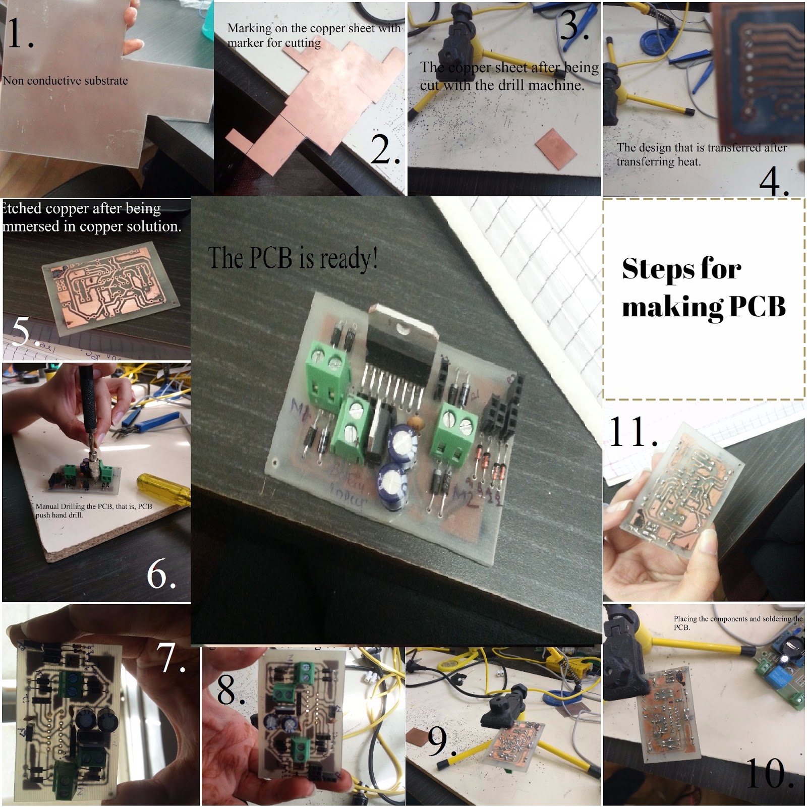
Figure 1: PCB making
And here it is, the PCB is ready for use.
A view to our PCB layout on the diptrace software can be seen below:

A view to our PCB layout on the diptrace software can be seen below:

Figure 2: Diptrace PCB layout
Diptrace Useful Link: http://diptrace.com/download-diptrace/
Wow! Thank you so much for the very informative blog post. I was wondering if I should use the DipTrace software. I had read about it on various forums and some people liked it while others did not. However, it looks like it did a fine job designing the printed circuit boards for your project. Good luck to you!
ReplyDeleteBrandi Bradley @ Rotax Metals
Thank you so much. It is user friendly.
Deletepcb design companyPCB design. Circuit Design SRL offers a complete range of Schematic Capture, Printed Circuit Board Design and Firmware Coding services. Embedded design projects, microcontroller, UART, CAN, RS-232
ReplyDeleteelectronic design companyPCB design. Circuit Design SRL offers a complete range of Schematic Capture, Printed Circuit Board Design and Firmware Coding services. Embedded design projects, microcontroller, UART, CAN, RS-232
ReplyDeleteHard disk drives that do not spin up after the power has been supplied can be diagnosed as PCB failure. Printed Circuit Board
ReplyDeleteI’ve read some good stuff here. Definitely worth bookmarking for revisiting. I surprise how much effort you put to make such a excellent informative web site. reproduce PCB Board
ReplyDeleteGreat insights on PCB designing! The breakdown of design steps and considerations for component placement and routing is very helpful, especially for beginners. If anyone is looking to turn these concepts into professional products, exploring reliable PCB designing services can really make a difference in efficiency and accuracy. Thanks for sharing this informative post!
ReplyDeleteThrough-hole printed circuit board assembly is known for its versatility and solid performance across multiple electronics projects. Choose TSTRONIC to get your designs assembled smoothly and effectively.
ReplyDeleteGreat breakdown on PCB designing! Getting those traces right is an art form. But man, ignoring DFM guidelines is a recipe for disaster, often leading to common pcb defects like solder bridging or acid traps. Appreciate the tips—definitely keeping these in mind for my next production run!
ReplyDeleteGreat blog on PCB designing! It explains the fundamentals in a simple and practical way, making it easy for beginners to understand the PCB design process. The step-by-step approach and clear explanations make it a valuable resource for electronics enthusiasts and students.
ReplyDeleteBentec Components & Trading Pte Ltd